How Can We Help?

You are here:
Print

This article describes two advanced features that are usually used with complex assemblies, such as Part Selector and QR Marker Placement.

Select Part is a tool that helps to change the part and model rotation for alignment. 

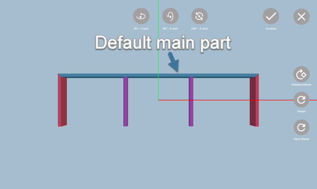
Main part is the one used for alignment with the real assembly – you always place the QR code on it. The default main part is usually the biggest one within the assembly model, and it is always highlighted in blue, while the other parts do not have a designated color. 
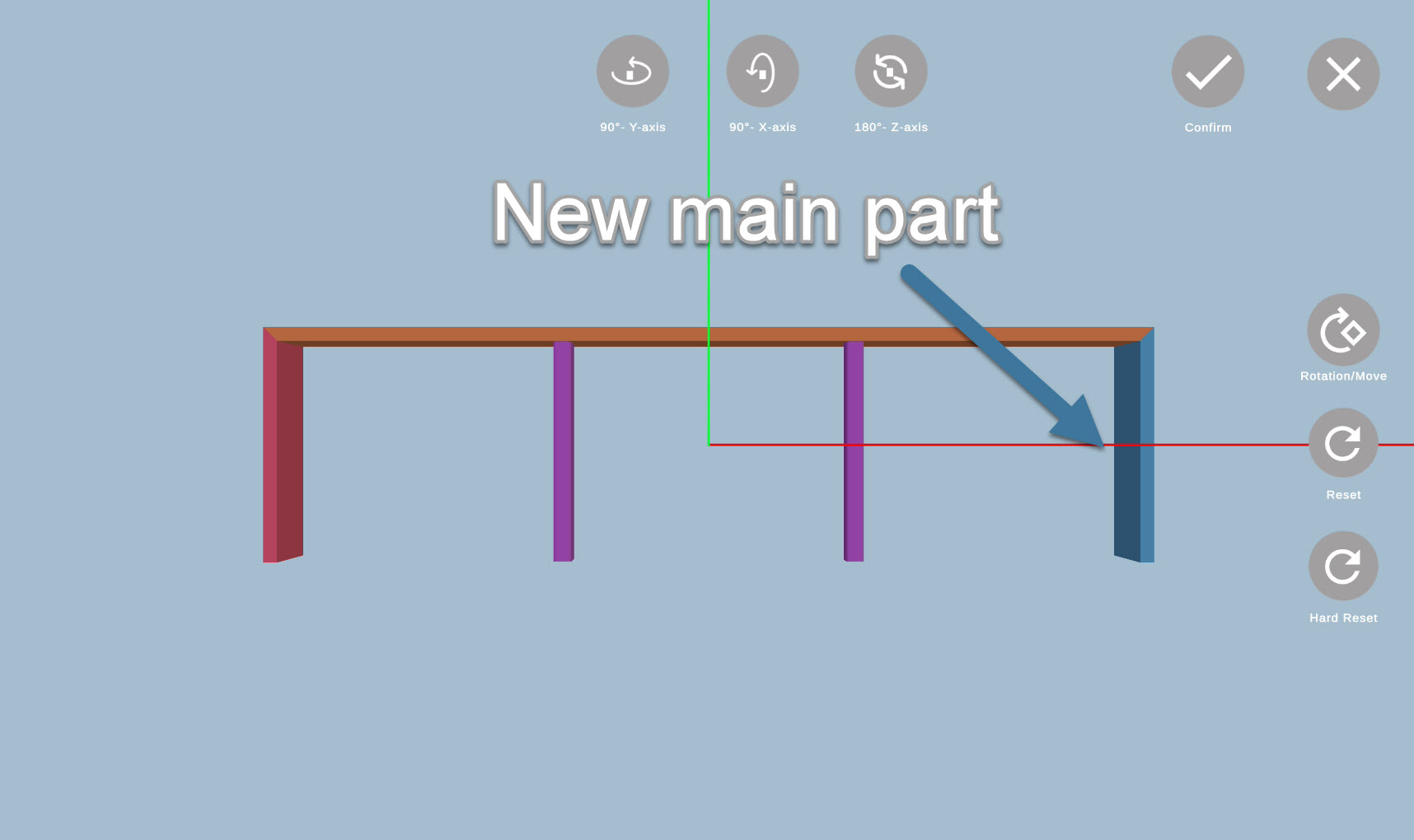
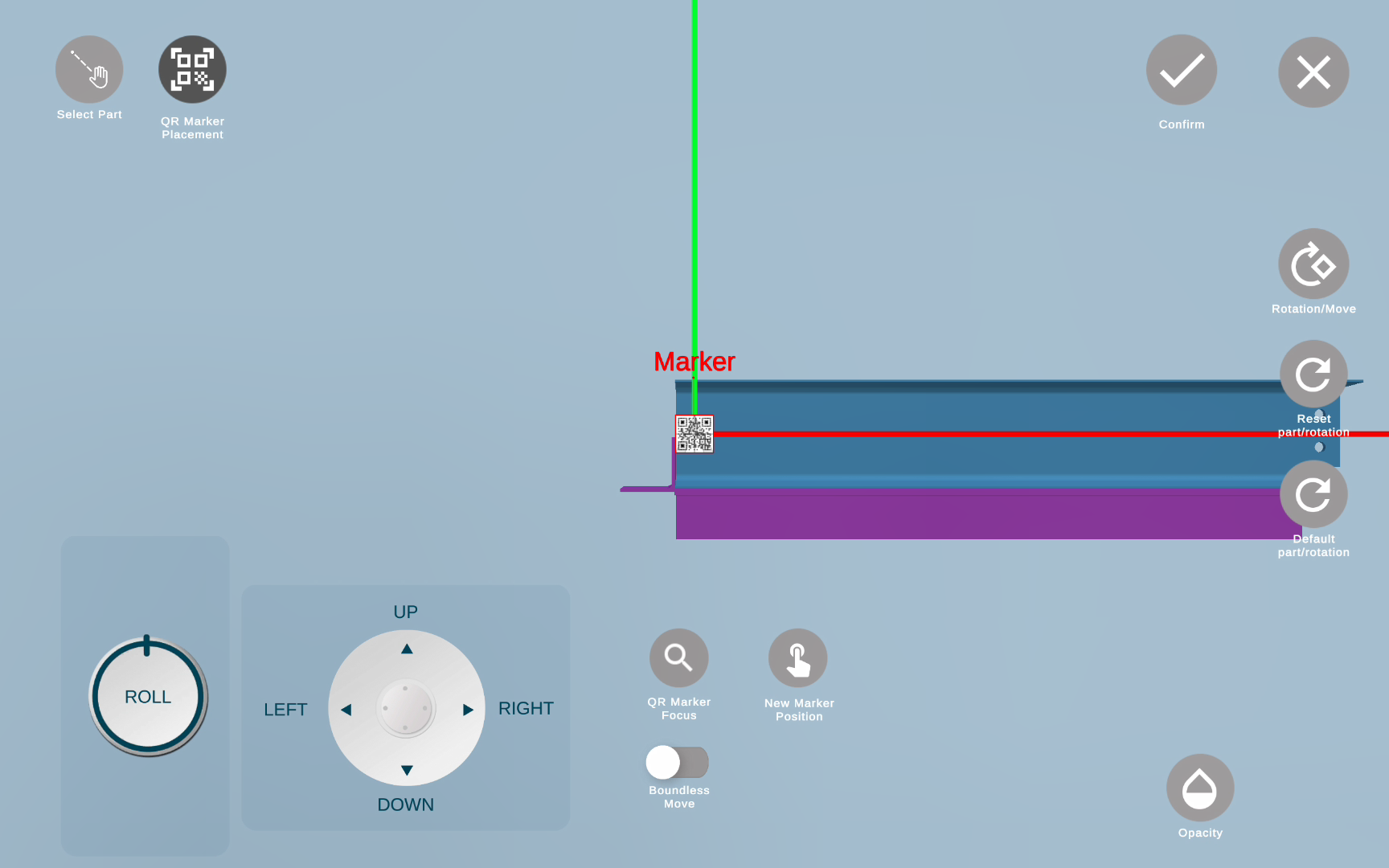
Once you click on Select Part button, you will see a new submenu with Controls buttons. To change the main part, rotate/move the model as convenient and tap of the part you want to have as main. 

While the main part is selected, make sure that the model within the 3D viewer has the same rotation as your actual assembly.

Please use only fixed rotation buttons: 
Warning

Free rotation will not change the assembly position for AR mode. It should be used only for viewing assembly from different angles. 

Also, note that you should place the QR code on the main part you want to align to, following the general rules for the QR code target.

Click here to learn more about QR code placement.

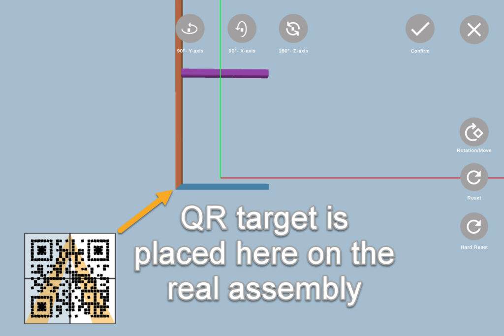
Once the assembly has the correct main part and rotation, click on the checkmark  and it will direct you to the QR marker placement.

Important

It's recommended to go to the 3d viewer and check that the main part of the assembly is correct, before the alignment process.

By default, you place the QR Marker on the end of the assembly (whether it’s right or left side of it) on the flat surface.

However, if the end of the assembly is not flat (i.e. curved beam) or there is not enough surface to place the QR code (i.e. rails), you can use QR Marker Placement feature to change the QR code position. 

Important

There is no need to use this feature for every assembly. Unless you need to more the QR Marker from the assembly left/right end, please just use the old workflow. 

Feature Access and QR Marker Automatic Adjustment

To access the feature, navigate to the 3D Viewer > Select Part, and choose QR Marker Placement QR button from there. 

Alternatively, it will open up after you confirm main part and rotation with the Part Selector. 

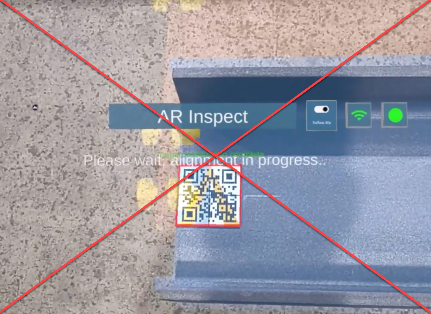
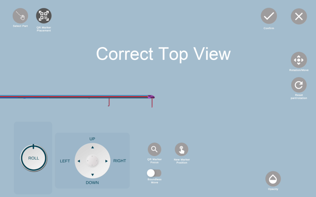
When you open this feature for the first time within the assembly, it will automatically align its position to the left end of the assembly, and if you are fine with QR Marker position, you can save it and go to the AR feature:

When you do this process within the 3D Viewer, QR Marker position is saved within the App, and you will not need to go through an automatic adjustment process within the AR feature, as it was before. 

Also, if it was adjusted once anywhere (AR or 3D), its position will be saved, and in case you need to align the same assembly again, QR Marker position will be saved as well. 


Manual QR Marker Placement

If you are not satisfied with automatic QR Marker position, you can click on “No” within the pop-up that will appear after QR Marker position is automatically adjusted. 

By clicking “No” you will see the pop-up informing you that you can now change the QR code position manually and show you a variety of tools for it: 

Warning

Use QR Marker Placement only when you adjusted rotation for the alignment of the main part within the Part Selector using fixed rotation buttons (90 and 180 degrees). 

If you need to adjust rotation after opening QR Marker Placement, go to Select Part first. 

Navigation

There are 2 ways of moving the QR code: 

  • Using Up-Down/Left-Right joystick;
  • “New Marker Position” button;

By tagging the joystick, you will be able to move the QR code into the corresponding directions, which is perfect for the small adjustments.

If you want to move the QR Marker to a totally different place, you can use “New Marker Position” button. 

Workflow: Set the QR code at a center of the model: 

  1. Use “New Marker Position” to move the QR marker to center. 
  2. Click on QR Marker focus to zoom into the QR code. 
  3. Use the joystick to correct the position.

Check the short video below:

You can also use:

  • “Rotation/Move” button on the right;
  • Roll on the left;
  • Zoom in/out with your fingers

for your convenience, to change the assembly angle or move the assembly on the screen if it’s too big. 

Please mind that 3 options abovr are used only for looking at the assembly, and will not actually change its rotation for alignment

Additional features

To make the QR Marker placement more convenient, you have a couple of additional features, such as: QR Marker Focus, Boundless Move, Opacity and Reset buttons. 

QR Marker Focus is handy when you need to quickly find/zoom in QR code position for micro adjustments or to confirm its position. 

qr-zoom

By default, you can only move QR Marker within the assembly main part border.

However, with such assemblies like rails or a thin column, you can use Boundless Move toggle to place QR code outside the assembly.

Warning

Please do not turn on Boundless Move unless it's absolutely necessary to place the QR code position outside assembly.

If you need to place the QR code on a different assembly part, please go to the Part Selector feature and change the main part to the one you would like to place the QR code on. 

Opacity is helpful when an assembly has a lot of parts, and you need to see the main part with the AR code through it. 

Click on the Opacity button and a bar with the toggle will appear allowing you to change the opacity level. 

Workflow: Rails and slim columns

“New Marker Position” button limitation.

The QR Marker Placement tool is created for working with curved assemblies, so it will be possible to place the QR code there. 

However, if you are working with the handrails and assemblies like slim columns, you need to understand the tool limitation. Since their surface is not fully flat, when you use “New Marker Position” and click on some new place, it will rotate the assembly to make the new position look “flat” with the “top view” of the main part. 

Most likely, this is not what you need, because the assembly will appear tilted in the AR features (Auto-Fab/Fab-Assist).

To, instead of using “New Marker Position”, tag the market with joystick Left & Right: 

If you clicked “New Marker Position” or used Up&Down by mistake and the assembly is tilted because of that, click on the “Reset” button on the left to reset the view, and use the joystick after that. 

Warning

All in all, working with rails and slim columns, do not use "New Marker Position", and only use the joystick Left-Right.  

Workflow: Part Selector & QR Marker Placement

Part Selector and QR Marker Placement are grouped together because they should be used one after another. 

Here is your workflow step by step: 

  1. Use Part Selector to choose the main part (highlighted in blue) which you will be using for alignment and placing QR marker. 
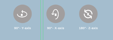
  2. Use Part Selector’s fix rotation buttons (90 and 180 degrees) to rotate the assembly as you need.
  3. Confirm your selection with the checkmark on the right.
  4. After that, you will be directed to the QR Marker tool. QR button
  5. Wait for the QR Marker to be aligned automatically
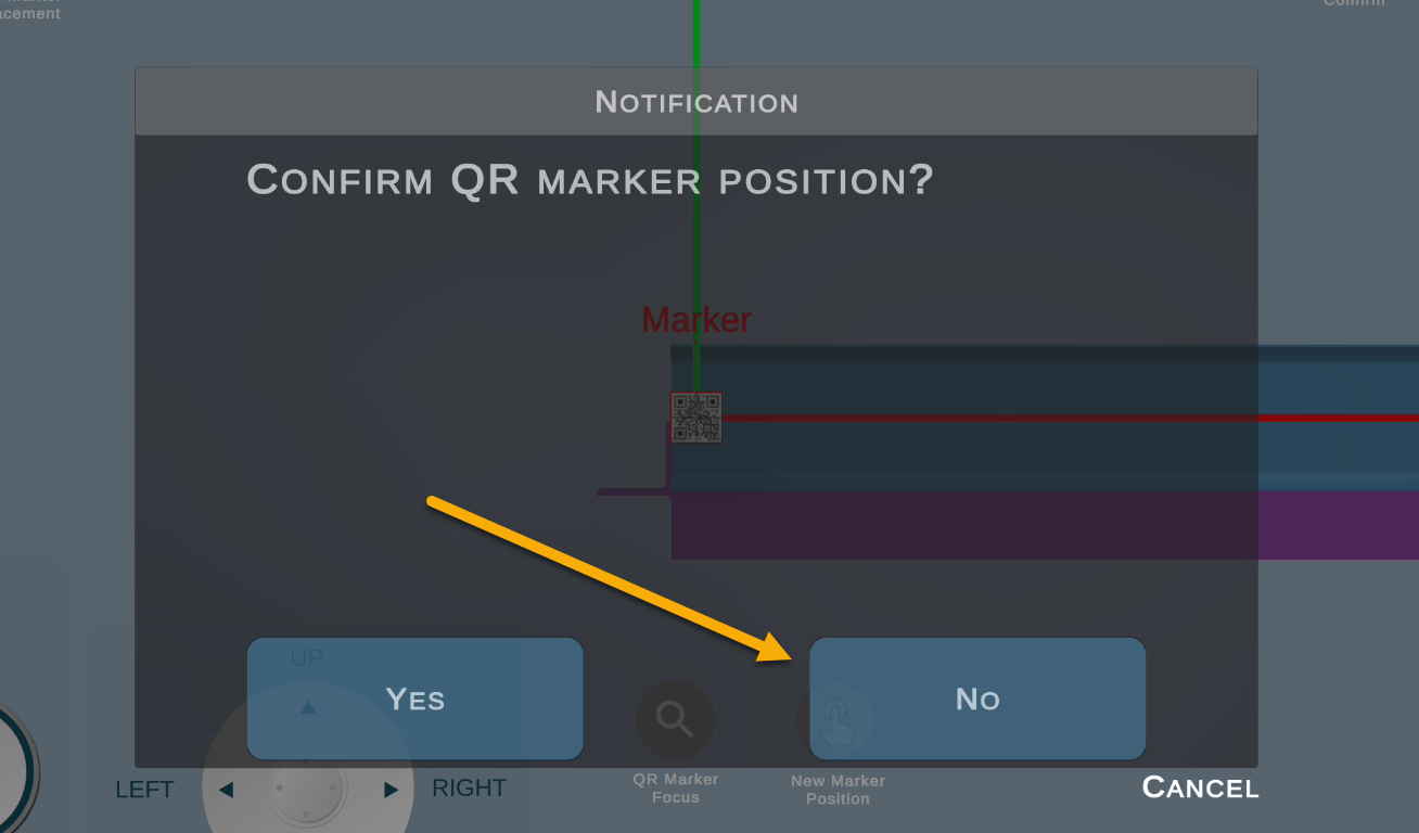
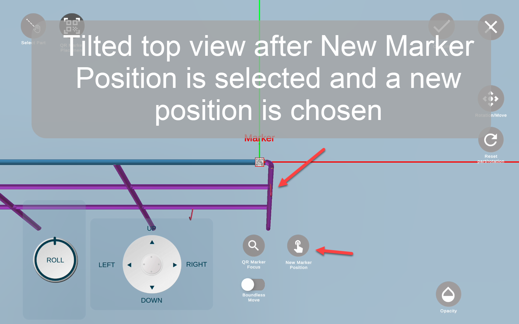
  6. Confirm the position, or change its position manually
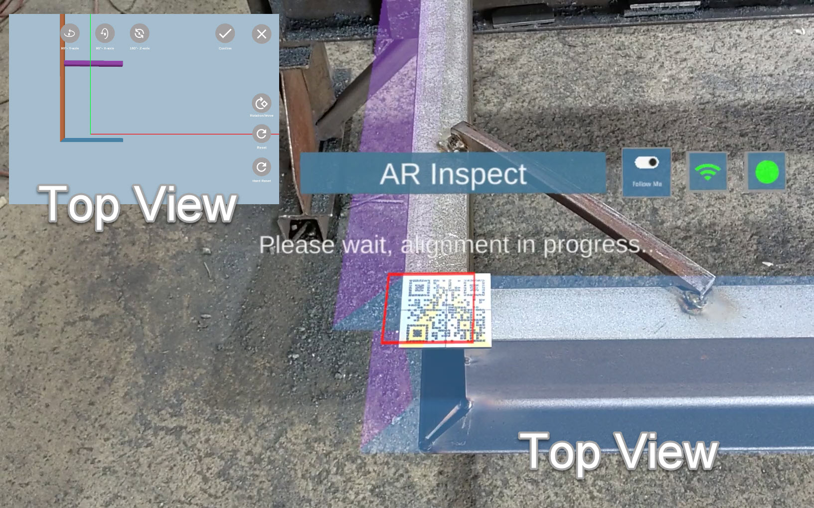
  7. Once the QR Marker position is satisfactory, click on Confirm  button again and start aligning the assembly with the AR mode. 


Check the described flow on the video below:

part-selector+qr
Tags:

Table of Contents

About Eterio Realities Inc.

Eterio Realities Inc. is a software development company that specializes in Augmented Reality for industry 4.0. Our flagship product, FabStation, uses break-through Mixed Reality technologies to visually place 3D assets into a worker’s normal workflow. This is done through the use of devices like the Hololens 2.

en_USEnglish