
How Can We Help?
Export Project Data: Tekla Structures with TSEP Plugin
To export all the required project files from Tekla Structures, there are two options:
- Download the Tekla Structures TSEP plugin and generate the correct project ZIP automatically;
- Piece the ZIP file together manually via individually exported files provided by your detailer.
It’s recommended to use TSEP plugin, and the process will be described below.
If you prefer to follow step-by-step instructions, please refer to this guide.
TSEP Plugin Installing and Overview
To export a complete project ZIP file from the Tekla Structures Fastation Tools – FabStationExport application follow these instructions:
The workflow to use the app is split into two steps:
- Export For Fabrication Data such as
- A KISS file;
- Assembly Orientation file;
- Shop drawing PDFs (General Arrangement / Erection drawings excluded).
- Export IFC Model of the parts that
- The detailer selected associated to the drawings being released for fabrication
- Any additional parts near or connected to that steel in the model for reference (i.e. concrete, joist, existing steel, or steel at match lines that have been previously released for fabrication or will be released in subsequent submittals).
Install and open the app in Tekla Structures by following the instructions in the video. You can download the FabStationExport V1.4 app via the link below. Make sure to unzip first before installing.
The application is supported in Tekla Structure versions 2017 and beyond and will not work in previous versions.
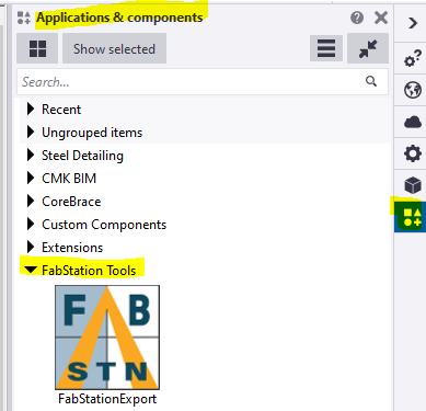
The tool can be found and opened from the Applications and Components panel at the right-hand side of Tekla Structures under the FabStation Tools group.
Double click on the icon to launch the tool.
Watch the video below for more information.
Step 1: Export For Fabrication Data
This step will create the KSS file and the drawing PDF files for export to the FabStation Web-portal.
1.1 Make sure numbering is up to date on all the parts that are associated to drawings being released for fabrication.
1.2 Make sure all the drawings being issued for fabrication are up to date.
1.3 If you are using Multi Drawings (multiple assembly marks on a 24X36 sheet), then check the Multi drawings option on the dialog box.
1.4 Enter the Package Zip File Name in the tool dialog box. If any invalid windows or file character names are used, they will be truncated by the tool.
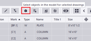
1.5 Open the document manager (formerly drawing list) in Tekla Structures and select all the assembly / multi and single part drawings being issued for fabrication.
1.6 Press the Select objects in the model for selected drawings button in the document manager (cube icon). This will select all the parts in the model associated with those drawings, which are needed in order to create the KISS file export.
1.7 Press the “1. Export For Fabrication Data” button. A KISS file, Assembly Orientation JSON file, and PDF drawings will be created in the FabStation folder found inside your Tekla Structures model folder.

Watch the video below for more information.
Step 2: Export IFC Model
This step allows the detailer to select additional parts that are near or connecting to the assemblies and parts that were released for fabrication.
Examples: joist, concrete, existing steel, steel at match lines being released in other submittal packages etc.
To proceed with this step, please perform the following:
2.1 Open a window/area with the project designs and select all the additional parts that you want to be included in the IFC model file export.
2.2 Ensure that all the parts associated with the drawings released for fabrication are selected, along with any additional parts you want to be exported for reference.
2.3 Once all the parts are selected, press the “2. Export IFC of Selected Area” button.
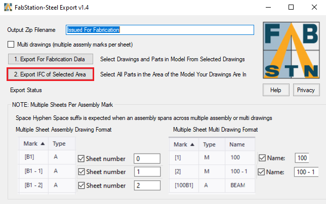
An IFC 2×3 SteelFabricationView IFC file will be exported, and then a zip file will be created in the FabStation sub folder found inside the Tekla Structures model folder. This is the zip file that will be imported into the FabStation Web-portal.
TSEP Plugin: Multi-Drawings and/or Multiple Sheets Per Drawing
This info is relevant to:
- multi-Drawings (multiple assembly marks on a 24X36 sheet);
- multiple sheets per drawing;
- a multi-sheet assembly drawing or a multi-sheet multi-drawing.
If you have cases where you need to span a single assembly mark across multiple assembly drawings or multiple multi drawing
- The Assembly Drawing mark will have a space hyphen space “– X” suffix in the document manager;
- Multi drawings will need to have a “ – X” suffix on all sheets except the first one.
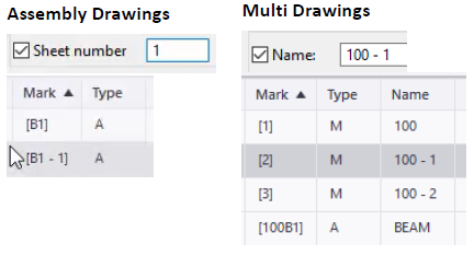
See examples above: essentially the last hyphen seen in the drawing mark / multi sheet name will be considered the sheet separator / delimiter even if the assembly / multi drawings already have hyphens in them.
In the multi-drawing example to the right, notice there is a sheet 100, which would be the first sheet that assembly drawing views will be linked to and will assign the multi number 100B1 to the assembly drawing and mark.
Any subsequent multi drawings for that sheet should be suffixed with “ – X”.
The tool will then recognize that these multi drawings are tied together and will be combined into one single PDF binder, 100.pdf in this example. When adding assembly drawing views to subsequent multi drawings like 100 – 2, 100 – 3, etc, do not use the link drawing views feature, use the copy drawing views feature.
If you use the link drawing views, it will output one of the “ – X” multi drawings as the main multi drawing in the KISS file.
If it's your first time assembling the files, use this form.
If you have assembled the files before, use this guide.
